220 volt breakers are commonplace in today’s homes. 220 volt electrical circuits power stoves, electric furnaces, central air conditioners, and water heaters.
While most homeowners won’t ever need to install a new electrical circuit, there are circumstances where a new 220V circuit may be necessary. For example, we installed radiant heated flooring in our basement.
Our system runs on 220 volts and requires a dedicated circuit for each of the 4 segments of the basement floor. We installed an electrical sub-panel for the heated floors in our utility closet that required the installation of a 60 amp 220volt breaker in the main panel and a run of #8 wire from the panel to the sub-panel.
Let’s take a look at the 220V breaker installation for this sub-panel. If you have a question on your own project, we recommend you visit our home improvement forums and ask your question there.
Cutler Hammer Breaker Panel
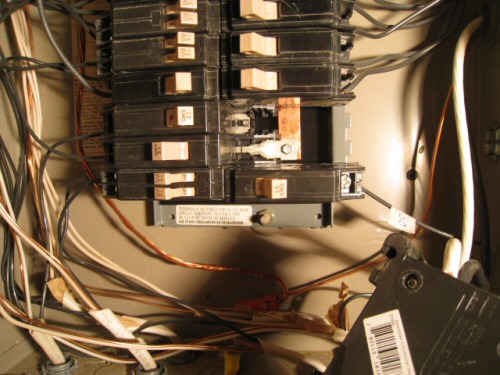
The picture below shows a Cutler Hammer breaker panel with the front cover off and one 220v breaker removed. This is the breaker we ultimately installed to run to the sub-panel for the floors.

There’s a few things to notice in this picture:
First, a 220V breaker takes up two slots. This is by design. If you look carefully at the picture, you’ll see that the connection on the top slot is coming from the left side of the panel, while the connection on the bottom slot is coming from the copper bar on the right side of the panel. As I discussed in our article on breaker panels, each of these copper bars is powered at 110volts to ground each, and they are out of phase. This results in 220volts of potential across the copper bars, and hence how a double-wide breaker can obtain 220volts.
Second, notice that on the back of the panel to the right of the copper bars you’ll see two grey teeth sticking off the back of the panel. These teeth align and hold the right side of an installed breaker. The breaker swings around these teeth and pushes tightly on to the connectors at the back.
Safety Note: The copper bar and metal connected to the copper bar are charged at 110V with a current limit equal to the total of the main breaker installed on the house (in our case, 200 amps). That’s a lot of current, and you would not want to touch this part of the panel.
220V Cutler Hammer Breaker
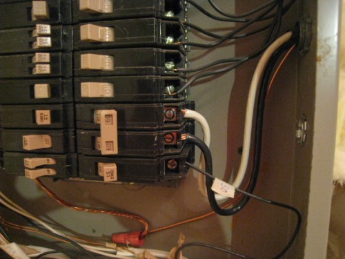
The picture below shows the 220V Cutler Hammer breaker installed in the panel.

Notice that there are three wires entering the panel for this circuit: a black wire, a white wire, and a ground wire that is nutted to another wire at the bottom of the panel.
The black and white wire each carry 110 volts to the sub-panel (they are wired to the left and right copper bars on that sub-panel). The ground wire is connected to the ground bus in the main panel and the ground bus in the sub-panel. We had a slightly short run of #8 wire and so had to use an equivalent wire gauge to make it to the ground bus. We took care to make sure the wire gauge was sufficient and the electrical inspector passed this configuration.
For 220 volt circuits, there is no ‘common’ or neutral wire. This is different than 110 volt installations where the white wire is neutral.
Steps to Install a 220 Volt Breaker
We’ve pretty much showed you what it takes to install a breaker. Here’s the steps:
Safety Tip: You must be a certified electrician in many areas to perform electrical work. Most jurisdictions require a permit to perform electric work, even in your own home. These instructions are for general information and you use them at your own risk.
- Turn off the main breaker.
- Make sure you have enough service to your panel to support another breaker. The total amps of the breakers in the panel can exceed the maximum amperage of the panel, but the anticipated concurrent load should not exceed 80% of the nominal amperage of the main breaker.
- Make sure you have 2 contiguous spots available. Note that just because the front of the panel has two ‘blanks’ doesn’t necessarily mean there are two real slots available in the panel. Remove the cover and ensure the slots actually exist.
- Knock out the metal covers on the panel cover to make the breaker slot visible from the front of the panel.
- Run appropriate gauge wire from the panel to the target service point. Make sure to leave enough wire to connect wires inside the panel to connect to the breaker and the ground bus. You should strip away the plastic shielding around the wires.
- Connect the ground wire to the ground bus.
- With the breaker removed from the panel: connect the black and white wires to the breaker (it does not matter which wire is connected to the top or bottom of the breaker). You should strip off only enough of the wire shield to fit the copper under the screw plate on the breaker. This minimizes the likelihood of a short.
- Push the breaker into the panel, ensuring you avoid touching any charged elements of the panel. (With the breaker off, only the wires at the top of the panel would be hot, but the bars in the back won’t be). In a Cutler Hammer panel, this is achieved by sliding the plastic grab hands behind the teeth on the outside of the connection and pushing the breaker into place.
- Update your breaker panel label with the new circuit information.
What About 220 Volt Circuits with 110Volt Service?
It is possible to have 220 volt circuits that can also provided 110Volt service to appliances. Older electric stoves used to use both 220 volt and 110 volt circuits. Modern stoves run almost exclusively on 220volts.
If we wanted to have the 220V circuit carry 110 volts, we would need to have 3-wire Romex (with black, white, red, and ground wires), as opposed to the 2-wire configuration shown here.
In that situation, the black and red wires would connect to the breaker, while the white wire (acting as neutral) and the ground wire would be connected to the ground bus in the main panel.
Note that if we were running to a subpanel, the neutral wire would not be connected to the ground bus in the subpanel but to a separate neutral bus. Ground and neutral should only be connected together in the main panel.
Got a question? Ask it in our home improvement forums and we’ll try to help!


You forgot a very important step: turn off the main breaker before you start wiring!
It’s too easy to accidentally touch the bus bar, or have a wire accidentally touch another live breaker and do anything from cause a big spark and some burn marks, to kill you. Before you stick your hands into the panel, cut the power. Use a non-contact electrical sensor (http://www.amazon.com/s/ref=nb_sb_ss_i_0_15?url=search-alias%3Daps&field-keywords=non-contact+voltage+tester&x=0&y=0&sprefix=non-contact+vol) that beeps/flashes to ensure the wire/equipment you’re working on is de-enegized. It’s sort of like the “measure twice, cut once” mantra: always test for power, even when you’re “sure” there is no power.
Greg, good addition. Post updated.