
We’re back with another Pro-Follow update. Steve Wartman and his crew are working through a basement remodel, and today’s article focuses on the electrical rough-in. If you’re just joining us, here’s what you missed:
In contrast to the electric rough-in for the other Pro-Follow basement, this job was relatively small and uncomplicated. The electrician only needed three additional circuits, and the breaker panel had several unused slots. There was no need for any new, dedicated circuits, and the whole job was completed with 14 ga. wire.
Step 9a: Plan the Rough-in & Pull Permits
Much like the other basement, the first step was to walk the basement and plan the locations of receptacles, switches and cable connections. Code dictates that receptacles be placed within 12′ of each other (even around corners) and 6′ of a door. All the boxes were mounted to studs 15″ off the ground, and if you look closely, you’ll notice that they protrude past the studs so as to be flush with the drywall (when it’s installed).
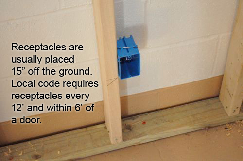
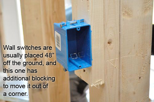
All the switch boxes were mounted 48″ off the ground.
Pro-Tip: New code requires a neutral wire be located at every switch, because neutral is required for some newer dimmer switches to function. In the past, an electrician could run a 2-wire “switch cable” from an overhead lamp down to the switch. This cable would bring power down to the switch on the white wire, and take “switched power” back to the lamp on the black wire. (This could be remembered with the saying “white going down, black coming back.”). This switching strategy does not bring a neutral wire to the box. When the crew runs Romex for lights in this basement, the circuit will originate at the sub-panel and travel to the switch boxes first, before heading on to the lights, resulting in a neutral wire at both the switch and the lights.
Pro-Tip: In some areas, homeowners can take a general electrical examination, and if they pass, pull their own permits and do the work themselves.
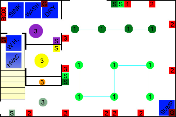
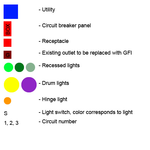
I put together a diagram of the basement showing the general locations of all the components the electrician installed.
Additional Information: Below are the National Electric Code’s rules for wire gauges and over-current protection requirements. Note that I’ve simplified this explanation to keep it brief. There are actually more complex restrictions based on the distance the wire is being run and the type of wire being used. However, for most residential installations, the following applies.
- 14 gauge wire – 15 amps maximum – standard lighting and receptacle circuits
- 12 gauge wire – 20 amps maximum – appliance circuits, kitchens, dining rooms, bathrooms
- 10 gauge wire – 30 amps maximum – water heaters, some HVAC equipment
The code generally allows for circuits to be loaded at 80%, meaning a standard 15-amp circuit can be loaded with 13 amps worth of fixtures and receptacles. The number of receptacles allowed on a circuit varies by district. Rather than specifying a limit for the number of receptacles on a circuit, the NEC uses a square-footage rating to determine the number of circuits required for a space. Generally, a safe assumption is that each receptacle will use 1.5 amps, which equates to eight receptacles per circuit for a standard 15 amp circuit. You should consult the NEC and your local code to determine the requirements for loading in your area.
Step 9b: Run Wire
With all the boxes mounted, the electrician selected a circuit, and starting at the furthest point, began running 14/2 (14 ga., 2 wire) back toward the circuit breaker.
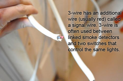
Pro-Talk: The term “2-wire” refers to a cable with a hot, neutral and ground wire within the wire sheathing. “3-wire” includes these wires an additional red wire called a traveler or signal wire, required in three-way switch configurations (where two switches control the same light), as well as in linked smoke detectors.
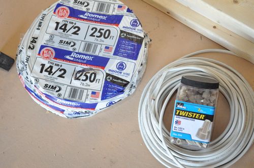
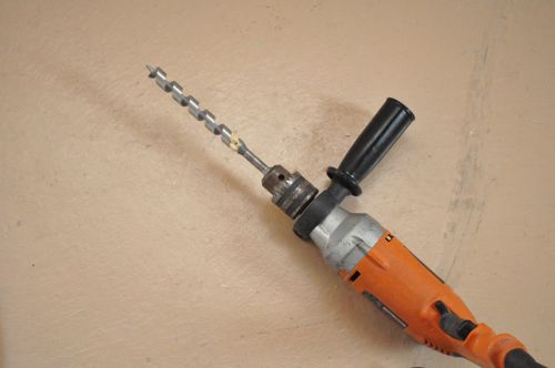
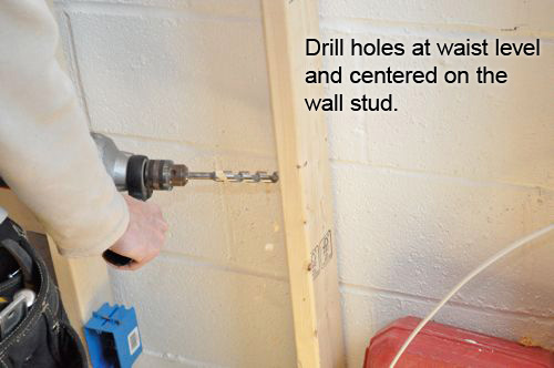
He drilled 1/2″ holes through studs, and sometimes utilized the space between the concrete and framed walls. Alternately, he could have drilled through the top-plate.
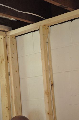
All the wires were secured with staples.
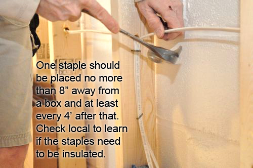
Pro-Tip: Check local code to learn if you need to use insulated staples to secure wire.
This basement has two, main banks of recessed lights and each one will have two switches to control them. This is beneficial because it enables the homeowner to turn the lights on or off from two points of entry. To achieve this, the electrician utilized 3-way switches and 3-wire between the paired switches.
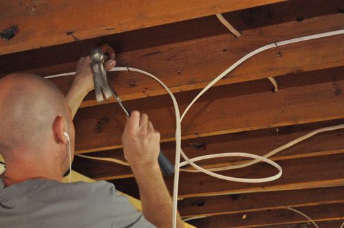
At this point, the electrician also ran the wires for the recessed lights. You can see that any holes drilled are several inches away from the bottom of the joist, and the wire is stapled in the middle of the joist.
Step 9c: Tie-in Cans, Receptacles, Switches
How a receptacle is tied-in varies slightly depending on the number of wires entering the box, and the example below shows three wires.
Pro-Talk: The term “tied-in” means ready for a receptacle or switch to be installed.
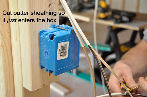
First, the electrician cut the outer sheathing at the point where the wires entered the box.
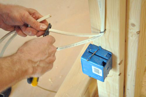
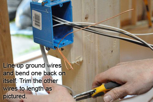
Next, he lined up the ground (bare copper) wires and doubled one back on itself, trimming the other wires to length.
After that, he twisted all the wires together very tightly and cut the end.
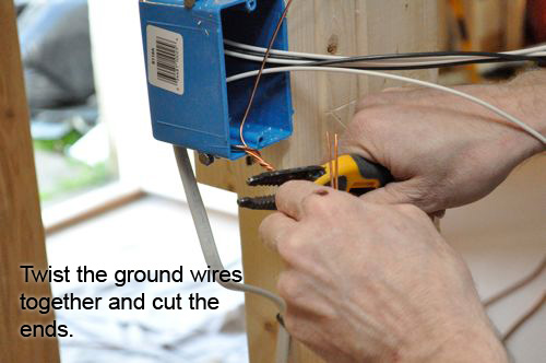
In effect, cutting the end created four separate wires (three entering the box and one “pigtail”) that are very securely spliced. Lastly, the electrician screwed on a wire nut.
Pro-Talk: A pigtail connection consists of a piece of electrical wire used to connect two or more wires.
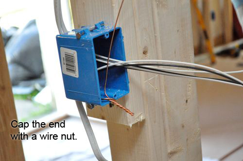
For this box, the electrician spliced three common wires (white wires) together. Next, he spliced two hot wires (black wires) together with a pigtail. This leaves one ground and two hot wires un-terminated which will (eventually) connect to the receptacle.
To splice the hot wires, he followed the same steps as the ground wires with a few important changes. The most obvious difference is that hot wires have insulation whereas ground wires do not.
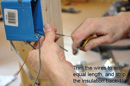
You can see how tightly the electrician twisted the wires before trimming the end and adding a wire nut. This results in a very strong splice.
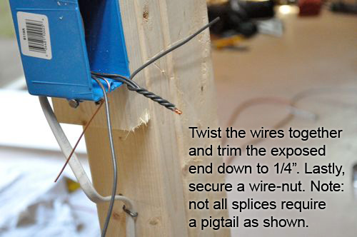
With all the connections in place, the electrician folded the wires into the box.

Most of the lighting in this basement will come from new-work, IC recessed can lights similar to the pictures below.
Pro-Tip: Check out our recessed light, table-top walk-through to learn more about a wiring recessed light circuit.
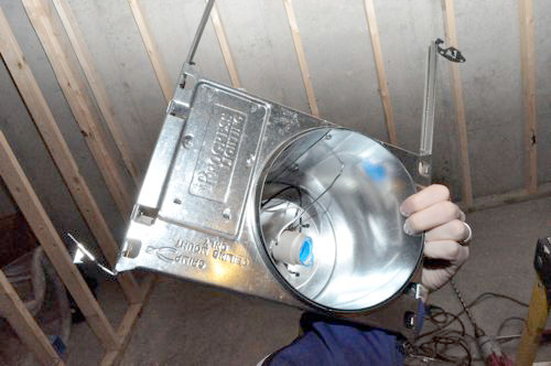
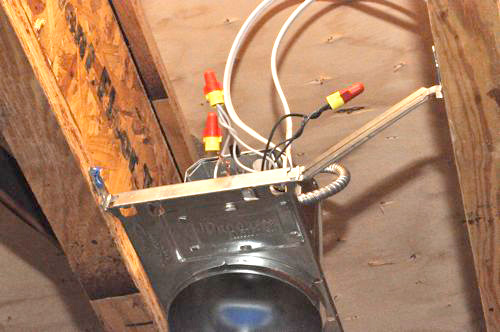
Pro-Talk: Recessed cans are rated IC (insulation contact) or Non-IC (no insulation contact) depending on whether the fixture can come in direct contact with insulation. Most Non-IC cans require a 6″ air gap between the can and the nearest insulation; whereas IC cans can have insulation packed tightly against them. IC cans are required in top-floor installations, but may be used in any installation.
Pro-Tip: Use remodel cans in finished spaces where drywall is already covering the studs. Remodel cans are similar to new construction cans except that they rest on the existing drywall instead of being fastened in between joists.
Step 9d: Wire New Circuit Breakers
Unfortunately, I was not able to be present when the electrician wired the new breakers and added them to the breaker panel. Even so, the work-flow consists of running the wire through a connector, into the breaker panel where the exterior sheathing is cut away. Next, the wires are “organized” along the perimeter of the breaker panel with common and ground wires connecting to the ground strip. Hot wires connect (usually with a screw) to a circuit breaker which push into place.
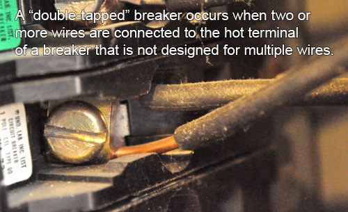
The electrician shared that a common problem he finds are “double-tapped” circuit breakers, and that is true of this breaker panel. This is an obvious red-flag and something that often comes up during a home inspection.
That’s it for this Pro-Follow update. Stay current with all of our Pro-Follows by becoming an RSS or email subscriber.


I’ve used the 3 wire to run power to a ceiling fan that also had a light on it. It was nice to only have to fish one wire.
I like that ground wire tip with folding one back and cutting the other. That looks like a time saver! Thanks!
I thought the same thing. It’s definitely a good trick to use, and I think it bundles the wires better.
I too will be using that in the future. Very cool! Seems like you wouldn’t be fighting the tiny little pigtail wire when you try to twist ’em because its all one wire (pigtail and one of the grounds anyway)
Another great post. How much should the boxes protrude past the studs to be flush with the drywall? I mean is there a standard measurement or did you have to line up a piece of sheetrock and eyeball it?
The drywall is usually 1/2″ and the boxes have a little bump-out that lines everything up.
Are there multiple bump outs for varying drywall thicknesses? I’m just thinking about other applications like garages and spaces that need double thicknesses of sheetrock for fire rating. Or a plaster and lath wall covering.
William, I have only seen boxes marked at 1/2″ for the thinnest drywall. if you want anything else you have to measure it. I’ve found that I can pretty accurately eyeball a 5/8″ placement with a 1/2″ marker, but it would probably be much harder going out a full inch. The other problem I’m thinking of is that I’m not sure most standard boxes would work because in order to get the box to stick out that much, the nails probably would miss the studs. There must be some other type of solution I’m not aware of. I’ve also seen some “box extenders” for when installing wainscoting. Maybe they would have some application here.
The bump outs only occur at 1/2″ but many of the boxes I’ve used have faint lines at 5/8″ and 3/4″ as well.
I’ve never seen uninsulated wire staples before. Neat.
I’ve seen ’em plenty and despise them. If they are too tight, they will eventually wear through the insulation and could become a shock/fire hazard. Thats just my opinion though as in most places they are perfectly legal
Jake – you are 100% correct. All the pros I’ve seen around here use ’em, but for the DIYer I like the insulated staples myself. Much easier to not screw things up.
Electrical work scares me, there is just so much to think about! Good thing we have a fabulous electrician to help us out with our old house.
Did the contractors actually measure 15 inches for the height of the boxes, or did they use something else as a guide? I’ve seen guys use their hammers to set the height (stand the hammer on the ground, set the box at the end of the handle), and it is definitely a time saver.
They actually did measure, and some electricians favor the folding, stick-rulers for marking out these measurements since they’re so repetitive.