
Welcome back to our latest Pro-Follow update. Last week I introduced a new basement remodel project with contractor Steve Wartman. He and his crew have finished framing the walls, and you can read all about that in the first installment of this series. Many homeowners and do-it-yourselfers have questions regarding how to address moisture in the basement, and today’s article will focus on vapor barriers. Additionally, I’ll be showing you how the guys ran air supply and return ductwork throughout the basement.
Vapor Barriers
Concrete slabs and concrete block walls are full of moisture, and over time and seasonal changes, concrete releases that moisture in the form of water vapor. Vapor barriers restrict the flow of air and water vapor, and when installed incorrectly can trap moisture leading to mold on studs, drywall and insulation.
There’s a lot of mis-information out there about vapor barriers. Fortunately, there is a great article from BuildingScience.com that dispels some of the mystery around vapor barriers. If you read through that article, you’ll see that vapor barriers originated in cold climates and have (sometimes needlessly) migrated.
Lstiburek defines the problem very succinctly a few paragraphs in, and it reads:
The fundamental principle of control of water in the vapor form is to keep it out and to let it out if it gets in. Simple right? No chance. It gets complicated because sometimes the best strategies to keep water vapor out also trap water vapor in. This can be a real problem if the assemblies start out wet because of rain or the use of wet materials.
It gets even more complicated because of climate. In general water vapor moves from the warm side of building assemblies to the cold side of building assemblies. This is simple to understand, except we have trouble deciding what side of a wall is the cold or warm side. Logically, this means we need different strategies for different climates. We also have to take into account differences between summer and winter.
Lstiburek, Understanding Vapor Barriers
The take-home message is that different climates have different requirements, and you should learn more about your specific location. Here in Maryland, we fall into the mixed-humid, Zone 4 (non-marine) climate, and Building Science recommends that we “do not require any class of vapor retarder on the interior surface of insulation in insulated wall and floor assemblies.”
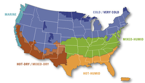
What Does This Mean?
These recommendations are just that- recommendations. It doesn’t mean that you can’t have a vapor barrier. However, in some climates, it’s an unnecessary cost, and contractors that are trying to stay competitive won’t include them. For that reason, Steve is not installing a vapor barrier in this basement.
Step 8a: Install the Air Supply Ductwork
Steve’s crew installed ductwork so that each room, window and door had an air supply. They also extended the return vent and will later create a new return for the first floor.
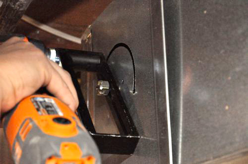
The guys started by creating the new air supplies, and they used a circle-cutter attachment to cut the new holes in the sheet metal.
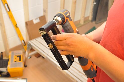
The ductwork will be 5″, but the connectors measure smaller than that, and they cut holes approximately 4-3/4″ in diameter.
The connectors have metal fins that you bend to hold the them in place, and everything is fastened with self-piercing, sheet metal screws, followed up with foil tape.
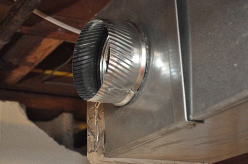
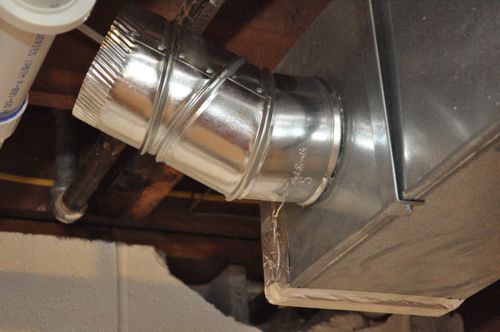
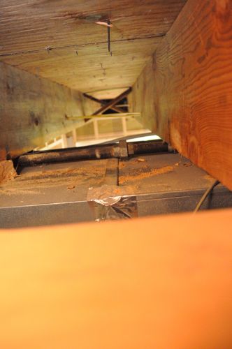
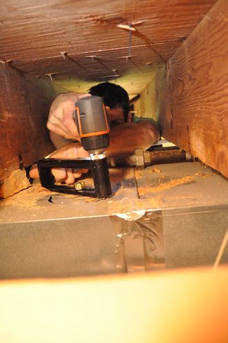
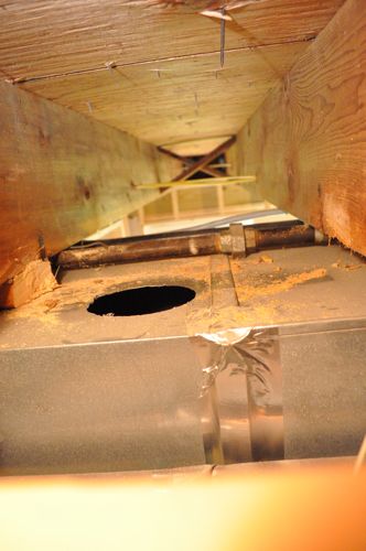
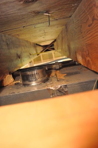
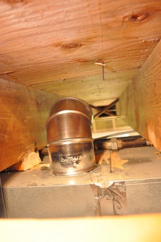
Next, the guys installed 5″, insulated, flexible ducts using a combination of zip-ties and foil tape.
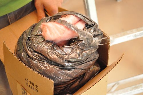

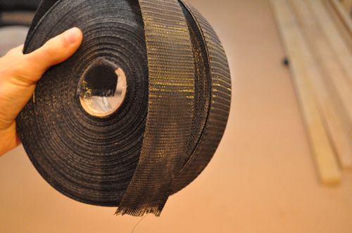
Steve’s crew secured the ductwork in place with a support webbing, stapled between the joists.
Pro-Tip: Flexible duct should be supported every 5′ or less.
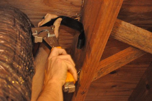
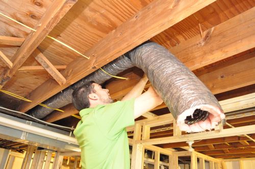
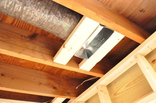
Cutting the ductwork the length with a utility knife, the guys attached the other end to a boot supported and fastened to adjacent blocking. These supplies are positioned about 2′ in front of the patio door and basement windows.
Pro-Tip: It’s important that flexible ductwork is fully extended and excess length is eliminated. Otherwise, air movement will be reduced.
Step 8b: Install the Air Return
If you read Day 1 of this project, you saw that a previous contractor eliminated the first floor air return. To rectify the situation, Steve and his crew are installing a new return, and to accomplish that, they need to extend the return air duct.
The guys started by assembling the first segment of the return air vent. It came in two pieces and the edges snapped together.
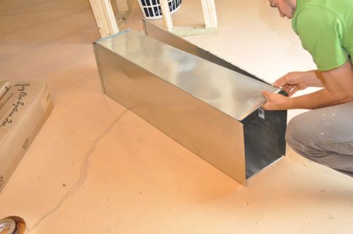
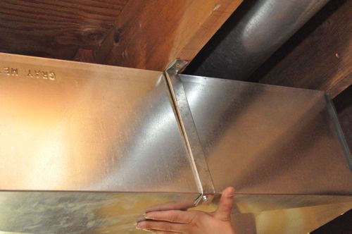
On the two wider edges, the ductwork has this overlapping metal channel called an S-slip for connecting the next segment.

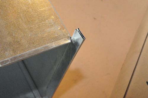
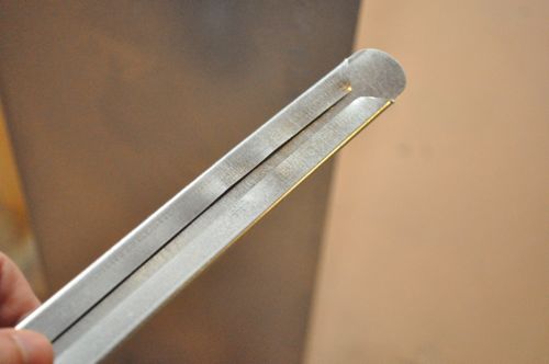
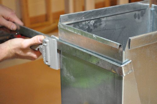
On the two shorter edges, the ductwork doubles-back on itself, and adjacent pieces are held together with drive cleats that slide in place.
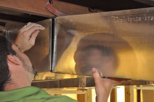
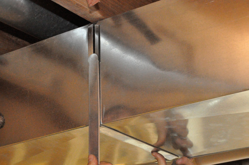
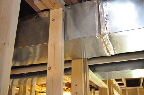
The whole setup is supported with duct hangers, screwed into the joists above, and all the joints are taped with foil tape.
Pro-Tip: Apply UL 181-rated mastic to seal sheet metal ductwork for a long-lasting, air-tight seal.
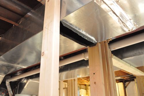
With the main return duct in place, all the guys need to do is cut openings for new vents and run them to the desired location. For the return pictured below, the guys will cut a hole in the drywall (after drywall is installed) and use the open space as the return.
That’s it for this installment. I hope you’ll check back for our next Pro-Follow update.


Great post. I’m going to need all this info when we finish our basement over the summer. I especially like the last photo. I never knew how HVAC guys put returns in the stud wall.
Cool, I’ve never run any ducting, so this is all news to me.
This may not make sense, or maybe I missed it during the planning & layout part…In picture 14, did they remove the crisscross pieces of wood or did they happen to find a beam that didn’t have any to begin with?
Good catch. I forgot to mention that they removed the cross braces.
Interesting our duct work in the basement is so sloppy I was just looking at it on the weekend so many air leaks.
The duct work in my basement was also leaking pretty badly. I would tape up a few spots with foil tape every time I went down to do a load of laundry so it didn’t get too monotonous. Eventually everything was sealed up. Now I’m going to try my hand at insulating the ducts as well.
I’m going to have to peek in my attic. I think our flexible ducts are supported further apart than 5′, and it’s causing kinks where the duct sags and the supports dig in. Our builder and his subcontractors were all window lickers on the short bus.
What exactly is the set-up they used to cut the circles? looks like the right angle drill attachment for the ridgid Jobmax. But they are obviously using some sort of spiral cutting bit in it.
They used a Ridgid JobMax with a right-angle attachment. If you look at the very first picture of it, you can see the sliding pin that anchors the center of the circle. I’m not sure about the bit, but I’d guess that you’re right. It looks like some sort of spiral cutter.
To use it, they’d first drill a hole for the pin, they with the pin in place, use the opposite end of the circle cutter to rotate it around.
Safe to assume the HVAC system was adequately sized for the additional runs? Would have been a significant additional cost if not.
Great stuff on the vapor barrier.
Yeah, the HVAC unit already had several branches for the basement. I think all together they added 2 more. With the flexible duct work it’s till an additional load, but this is something they took into consideration.